Change the ventilator setting
Start-up
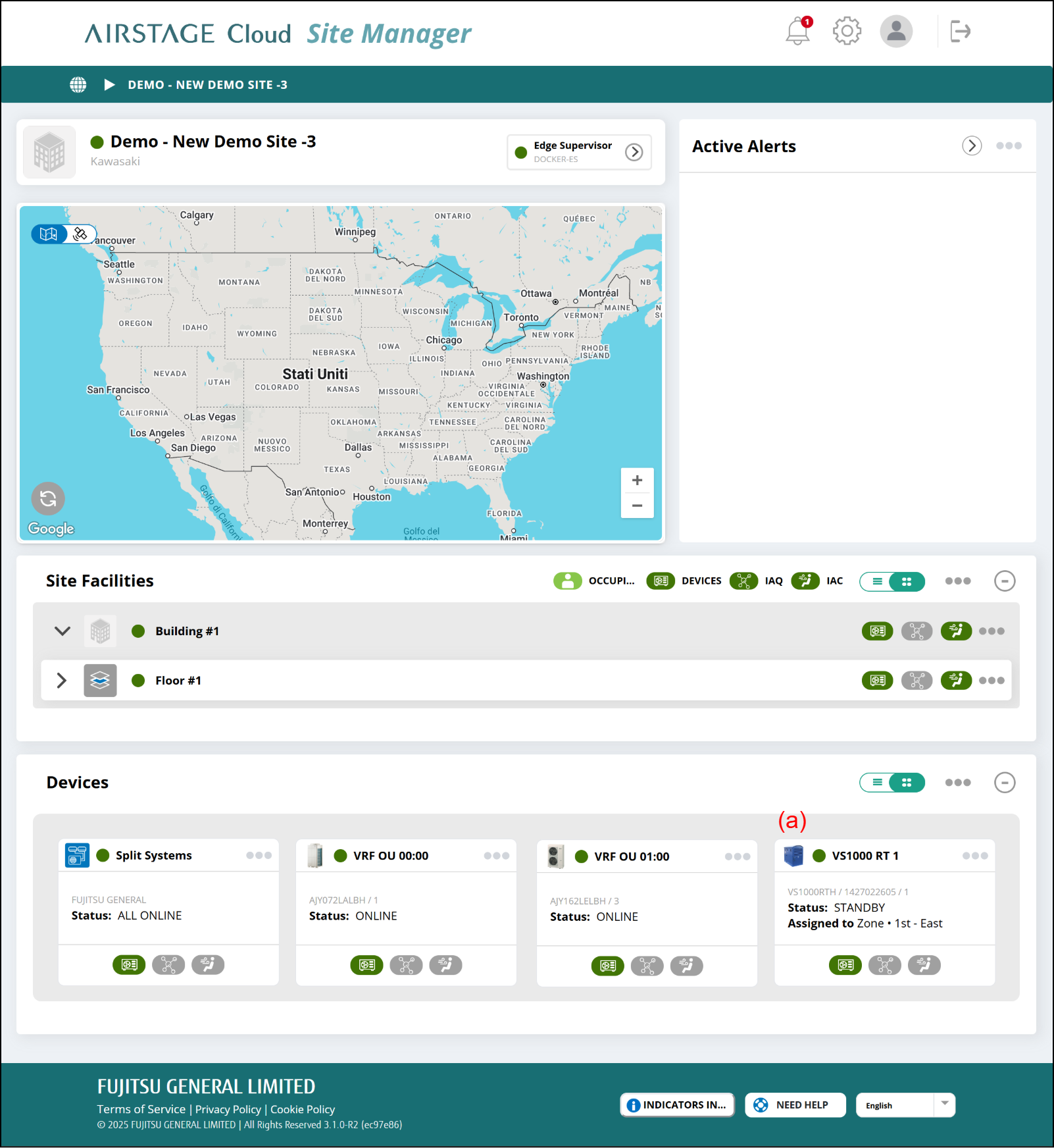
When Ventacity ventilator is connected, monitoring/control and schedule operation can be set.
- Select the Image Link (a) on “Site Dashboard” screen.
Ventilator setting screen
Ventilators are set.
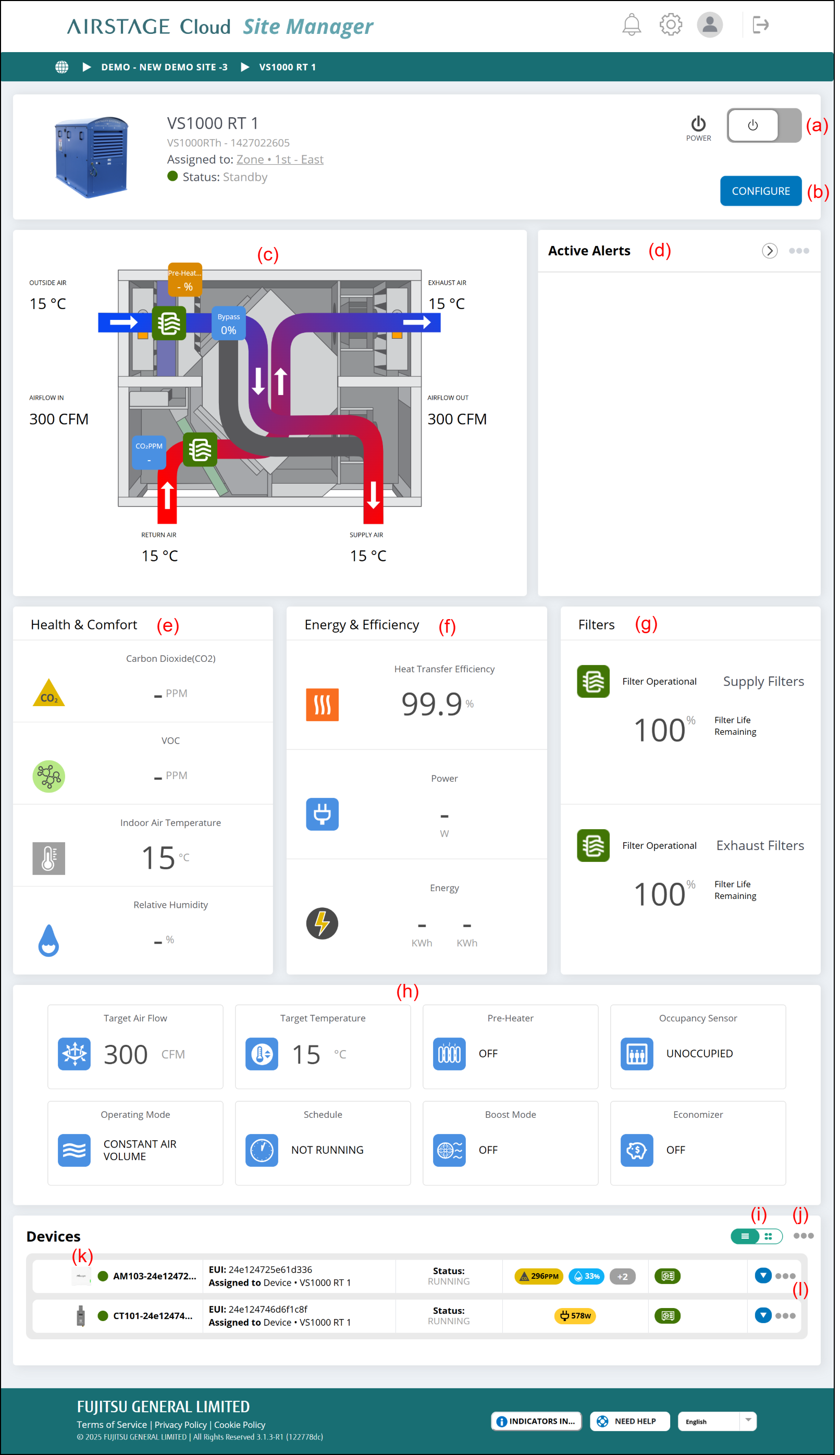
(a) Power button
Changes Start/Stop of ventilator.
(b) [CONFIGURE] button
Displays the "Ventilator configuration" window.
(c) Configuration diagram
| Outside Air | Fresh outside air entering the HRV/ERV |
| Exhaust Air | Unnecessary air exhausted from HRV/ERV after heat recovery |
| Return Air | Air coming out of the building |
| Supply Air | Fresh air entering the building after heat exchange |
| Pre-Heater | Defrosting and anti-freeze heaters |
| Bypass | Bypass damper for temperature control |
(d) Active Alerts
Alerts appears in necessary. For details, refer to "Alert and notification".
(e) Health & Comfort
| Carbon Dioxide (CO2) | Displays CO2 concentration when the CO2 sensor is connected. |
| Volatile Organic Compounds | Displays VOC concentration when the VOC sensor is connected. |
| Indoor Air Temperature | Displays the temperature of room temperature sensor. |
| Relative Humidity | Displays the humidity when the humidity sensor is connected. |
(f) Energy & Efficiency
| Heat Transfer Efficiency | Displays the heat transfer efficiency. |
| Power | Supported in the future |
| Energy | Supported in the future |
(g) Filters
Displays the filter replacement indication.
(h) Monitor for settings
| Target Air Flow | Displays the setting target airflow. |
| Target Temperature | Displays the setting target temperature. |
| Pre-heater | Displays ON/OFF for pre-heater. |
| Conditioner | Displays whether the conditioner is currently operating or not. |
| Occupancy Sensor | Displays the occupancy state of occupancy sensor. |
| Operating Mode | Displays the setting operation mode of ventilation. |
| Schedule | Displays ENABLE or DISABLE for Schedule. |
| Boost Mode | Displays the setting condition for Boost Mode. |
| Economizer | Displays the setting condition for Economizer. |
(i) Display switching button
Switches between card and list display.
(j) Link menu
- [Add Device]
Displays the "Add device" window.
(k) Image link
Depending on the type of device clicked, different “View Device” screen is displayed.
(l) Link menu
- [REMOVE]
A confirmation window is displayed. When [OK] is pressed, the Device is deleted.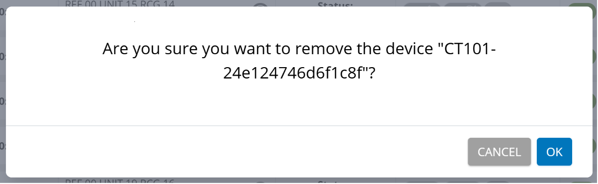
Ventilator Configuration window
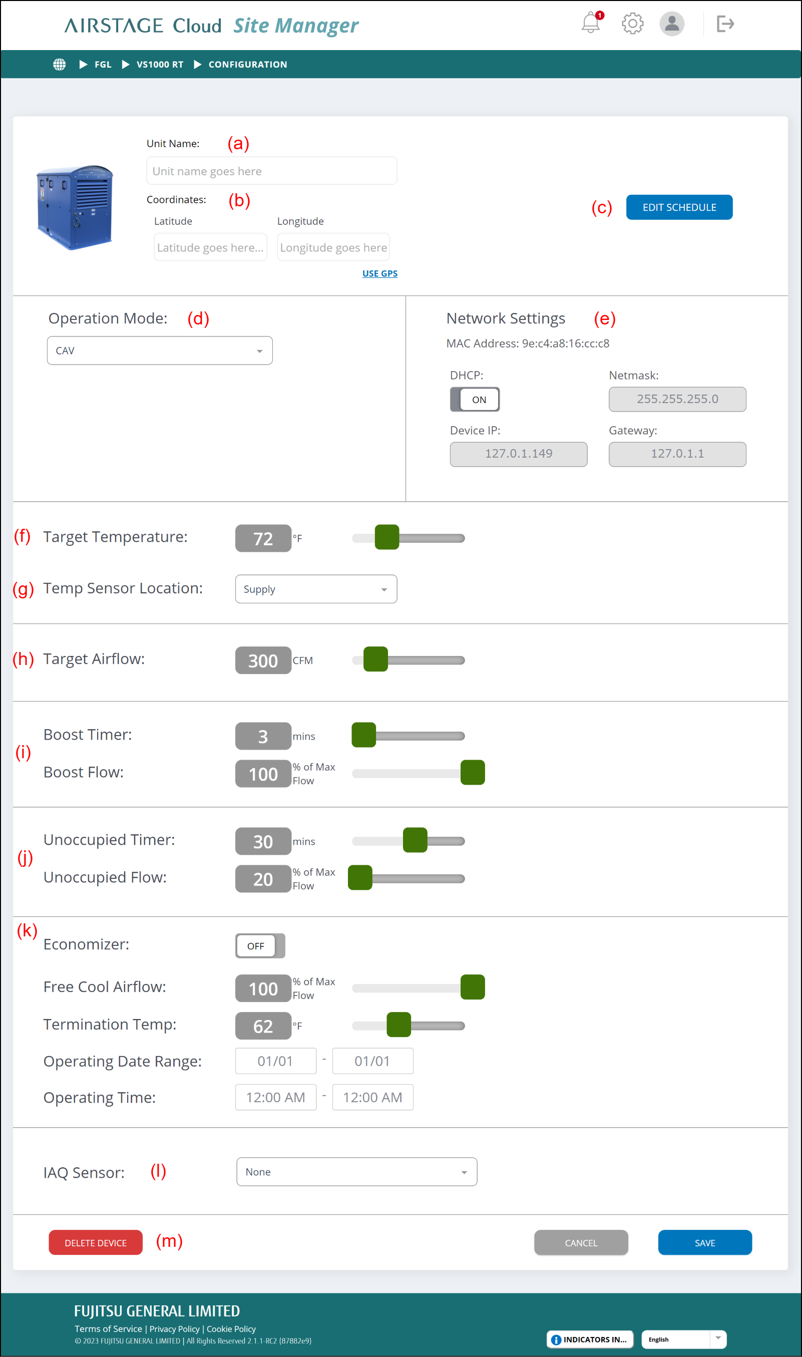
(a) Unit Name
Sets the unit name.
(b) Coordinates
Sets the coordinates of ventilator. When the coordinates are set, they are displayed on the map of Site Dashboard.
(When USE GPS is clicked, your coordinates of the current location can be obtained.)
(c) [EDIT SCHEDULE] button
Displays the "Ventilator schedule setting" window.
(d) Operation Mode
Sets the operation mode. The following types of operation modes can be set.
| CAV (Constant Air Volume) | This mode operates at a constant fan speed. Fan motor control depends on the set value of target airflow. |
| VAV (Variable Air Volume) | This mode maintains constant air pressure in duct by raising or lowering fan speed. Fan motor control ignores the set value of target airflow. |
| DCV (Demand Control Ventilation) | This mode varies fan speed based on indoor air quality sensor values. For example, when CO2 is high, the fan will speed up to try to lower it. When the CO2 goes down, the fan will slow down again. Fan motor control ignores the set value of target airflow. |
(e) Network Settings
Displays the network settings of ventilator.
(f) Target Temperature
Sets the target temperature.
(g) Temp Sensor Location
Sets the sensor of target temperature. The followings can be selected.
-
- Supply duct
- Extract duct
- Room
- None
(h) Target Airflow
Sets the target airflow. For CVA, Operation Mode is used.
(i) Boost Timer/Boost Flow
When Boost Mode is instructed, Boost Flow is operated temporarily for the time of Boost Timer.
This function is not provided depending on the model.
(j) Unoccupied Timer/Unoccupied Flow
When the occupancy sensor is connected to the ventilator, this function can be used. During the time set by Unoccupied Timer, the occupancy sensor always monitors whether the room is unoccupied or not. When the room is judged to be unoccupied, the ventilator operates at the Unoccupied Flow value.
The temperature cannot be set while the unoccupied detecting mode is operating.
This function is not provided depending on the model.
(k) Economizer
Economizer is a free cooling function that pre-cools the building in advance using cool air at night during the warm season.
- Some conditions must be satisfied to operate in the Free Cooling mode.
- For details of the transition conditions, refer to the manual of ventilator.
- During Free Cooling mode operation, the unit operates at the setting Free Cool Airflow.
- Free Cooling mode stops under the following conditions:
- The current time is out of range.
- Room temperature ≤ Outside air temperature
- Room temperature ≤ Termination temp.
- Operation is stopped by user.
(l) IAQ Sensor
Selects the sensor type connected to ventilator.
When the sensor is not connected, select “None”.
-
- CO2 2000
- CO2 1000
- RH
- VOC
- 0_10V
- None
(m) [DELETE DEVICE] button
Deletes the ventilator and removes it from the controlled devices.
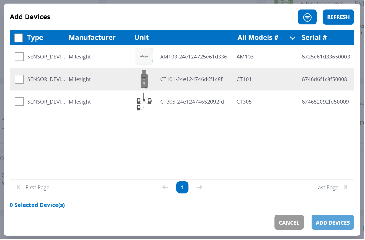
Add Device Window
Select the Device you wish to add and press the [ADD DEVICES] button to add LoRaWAN Device.