Perform the setting change or removal for Roof Top Unit
Roof top unit Dashboard detail setting screen
Start-up
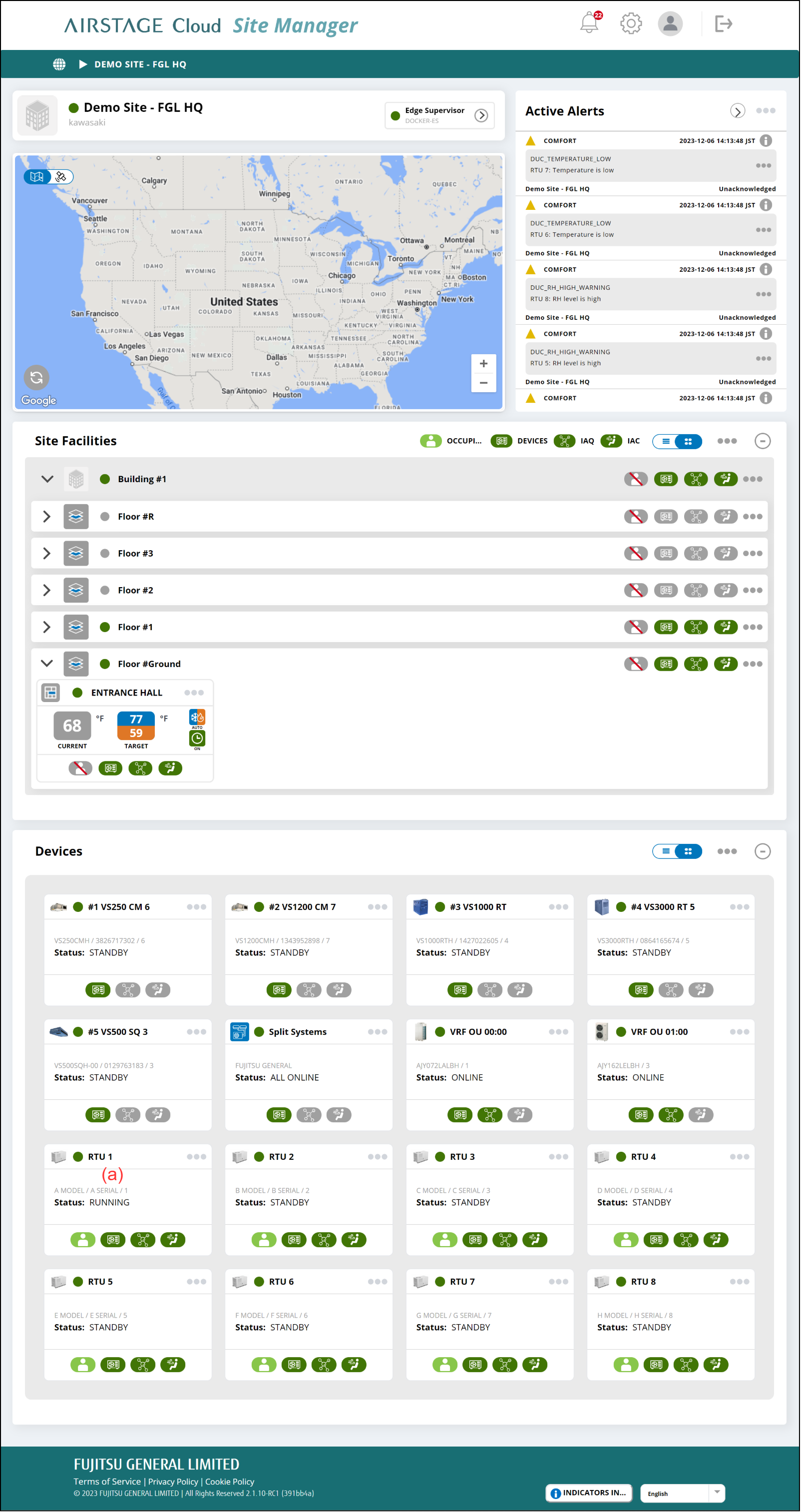
- Select the Image Link (a) on “Site Dashboard” screen.
Roof top unit Dashboard screen
Roof top unit can be set.
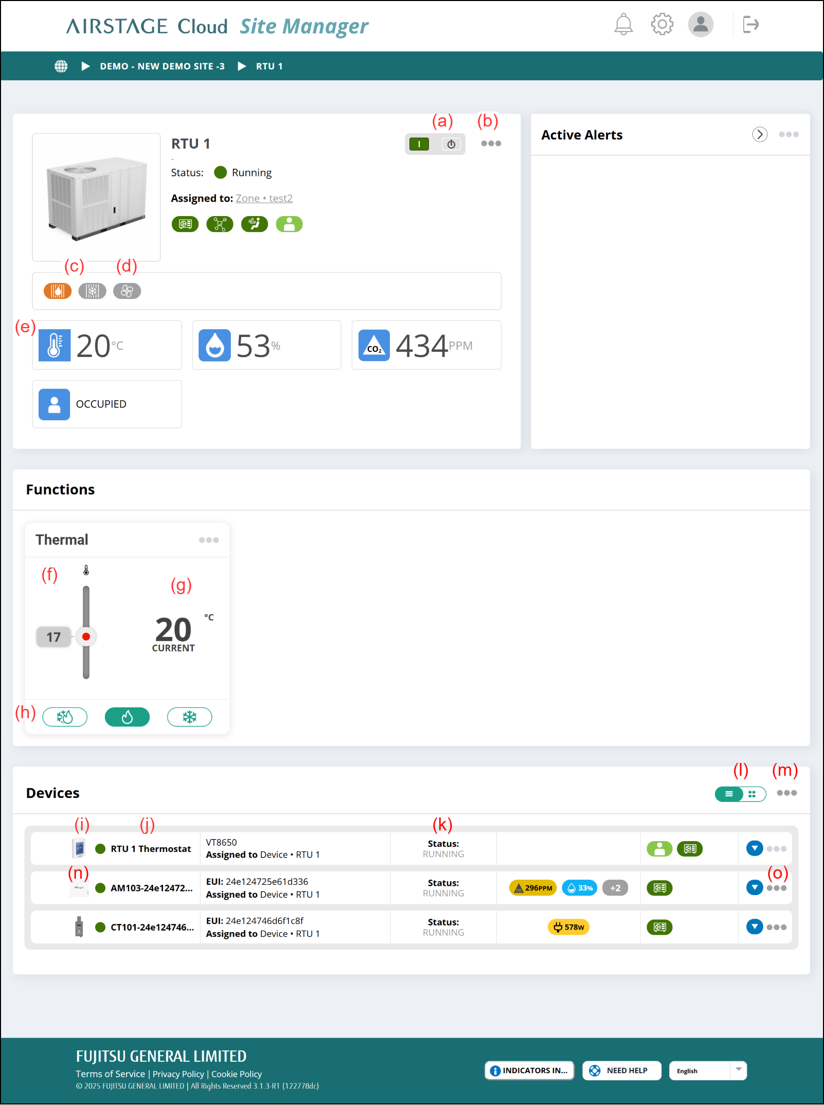
(a) [Stop/Start] button
Operation Stop/Start
(b) Link menu
- [Configure]
Displays the "Roof Top Unit Configuration" window.
(c) Coil Status
Displays the current coil status (operating mode).
- Cool : the Cool blue badge and the Heat gray badge will be displayed.
- Heat : the Cool gray badge and the Heat orange badge will be displayed.
- Off : the Cool gray badge and the Heat gray badge will be displayed.
(d) Fan Indicator
Displays the current fan status.
- Green : Fan running
- Grey : Fan standby
(e) RTU conditions
Displays the values obtained from the Smart thermostat.
|
|
Room temperature |
|
|
Relative humidity |
|
|
CO2 concentration |
|
|
Human sensor |
(f) Setting temperature
Sets the setting temperature. When the operating mode is Auto, set the cooling temperature and heating temperature.
(g) Room temperature
Displays the room temperature.
(h) Operating mode
Sets the operating mode.
(i) Image link
Displays "Smart Thermostat Dashboard" screen.
(j) Smart thermostat condition
|
|
Normal status |
|
|
Warning issue |
|
|
Critical issue |
|
|
Object is in pre-install status |
(k) Smart thermostat status
| Running | Operating |
| Standby | Operation is stopped. |
| Offline | Offline status |
(l) Display switching button
Switches between card and list display.
(m) Link menu
- [Add Device]
Displays the "Add device" window.
(n) Image link
Depending on the type of device clicked, different “View Device” screen is displayed.
(o) Link menu
- [REMOVE]
A confirmation window is displayed. When [OK] is pressed, the Device is deleted.
Roof Top Unit Configuration window
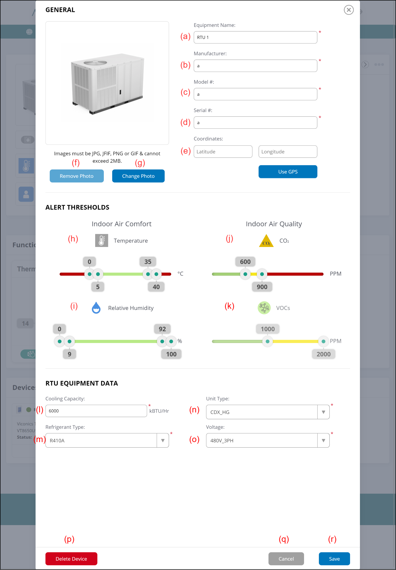
(a) Enter the Equipment name.
(b) Enter the Equipment Manufacturer name.
(c) Enter the Equipment Model name.
(d) Enter the Equipment Serial number.
(e) Set the coordinates of the RTU by either of the following methods.
- Input the latitude and longitude.
- Select [USE GPS] button to acquire the present location information.
After setting the coordinates, the location of the RTU is shown on the map of the "Site Dashboard" screen.
(f) [Remove photo] button
Remove the photo of the Roof top unit.
(g) [Change photo] button
Sets the photo of the Roof top unit.
(h) Temperature Alert threshold
Move the sliders to set the thresholds for each value.
Each color means the severity level as follows;
- Green: None or Low
- Yellow: Middle
- Red: Critical
An alert appears on the "Active Alerts" area when the Roof top unit conditions reach the Middle or Critical severity level.
The value is compared with the value of "Roof top unit Conditions" in the "Roof top unit Dashboard" screen.
(i) Relative humidity Alert threshold
Same as (h).
(j) CO2 Alert threshold
Same as (h).
(k) VOC Alert threshold
Same as (h).
(l) Enter the Equipment Cooling Capacity.
(m) Select the Equipment Refrigerant type.
(n) Select the Equipment unit type.
(o) Select the Equipment voltage information.
(p) [Delete Device] button
Delete this Roof top unit
(q) [Cancel] button
Cancel the Setting.
(r) [Save] button
Save the Setting.
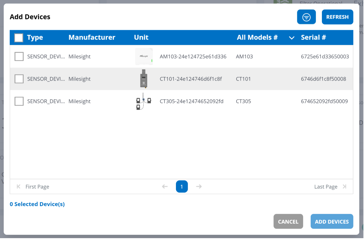
Add Device Window
Select the Device you wish to add and press the [ADD DEVICES] button to add LoRaWAN Device.